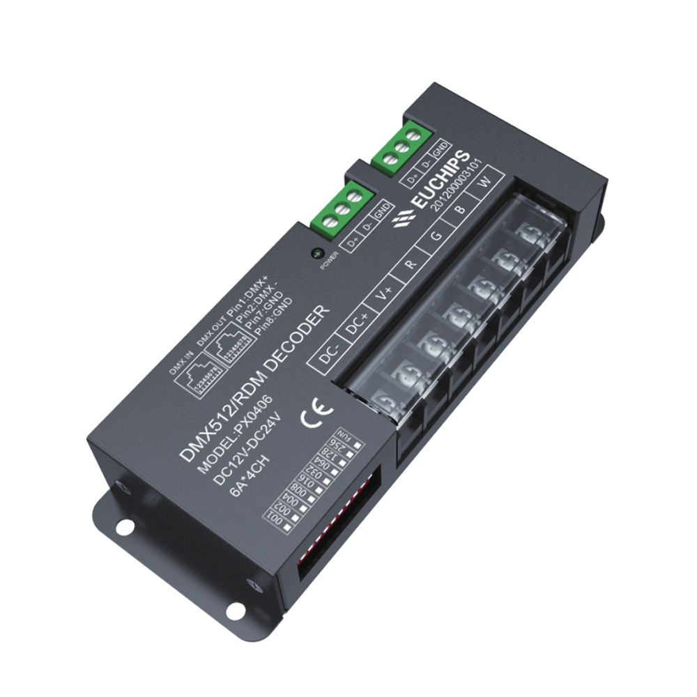
12-24VDC 6A*4ch DMX Decoder PX0406
Summary
Welcome to use PX series DMX512/RDM decoder & driver. PX series adopt the advanced micro-computer control technology and converted the DMX512,RDM/2009 digital signal widely used in international to the PWM control signal. 1~4 channels output for option and each channel able to achieve 256 gradations of controlling, and also it can be used as the connector of PC digital light controller and analog light modulator. It is mainly used for the controlling of buildings & lights applied LED.
Technical Paramaters
| Model | PX 0406 | |
|
Outpu t |
Channels | 1-4 |
| Voltage | 12-24VDC | |
| Curren t | 6A*4CH | |
| Power | 288W(12V)/576W(24 V) | |
| Input | Voltage | 12- 24VD C |
| Standby los s | < 1W | |
| Control sig nal | DMX512 1990/RDM 2 009 | |
|
Othe rs |
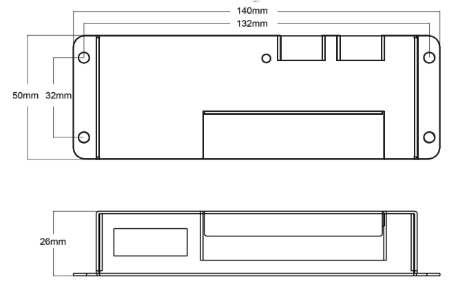
Dimension | 140*50*26mm( L * W* H) |
| Packing siz e | 145*56*32 mm( L * W* H) | |
| G.W. | 240g | |
| Operation temperatur e | - 20 - 50℃ | |
| Relative humidity | 20% - 90%R H | |
Dimension(mm)
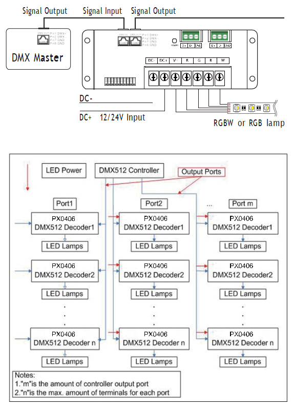
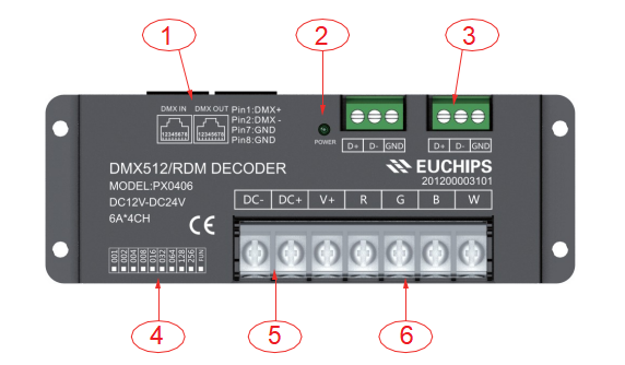
Interface Description
(1) RJ45 Signal input and output interfaces
(2) Signal light
(3) Euro terminal blocks
(4) Address setting interface
(5) Power input interface
(reverse connection of input will damage thedriver, make sure the wiring is correct before power on.)
Remark:
Connect the anode and RGBW wire of common anode RGBW module to the output interface of decoder directly; Connect the anode wire of single-color module to V+ on decoder, and connect the cathode wire to one of RGBW pin according to the LED's color; Connect several colors single-color module to one decoder, please connect their anode wires to V+ pin on decoder.
DIP Switch Setting
|
|
DIP1 |
DIP2 |
DIP3 |
DIP4 |
DIP5 |
DIP6 |
DIP7 |
DIP8 |
DIP9 |
DIP10 |
|
OFF |
0 |
0 |
0 |
0 |
0 |
0 |
0 |
0 |
0 |
NA |
|
ON |
1 |
2 |
4 |
8 |
16 |
32 |
64 |
128 |
256 |
FUN |
DIP1~9: Setting the first DMX address of device,the sum of number showed in the table above is the first DMX address of device.
In DMX mode, the effective address is 1-511, and 511 is for fixed mode (511 means output RGBW gradient).
When the address is 0, the default is RDM mode. DIP10: FUN is 120 ohm terminal resistance.
1) Use the CAT-5 cable or three-core shielded cable as DMX512/ RDM signal cable,and DMX512/RDM signal has the positive and negative signal. While welding the DMX512/RDM signal cable plug, there must pay much attention to distinguish between positive (+) and negative(-), and then connect the DMX512/RDM signal cable with the corresponding input interface of PX0406 correctly.
2) Refer to “DMX Series of address dial code table” to set DMX address by dip-switch.
3) Connect a signal terminal at the end of the whole connection.
Wiring Diagram