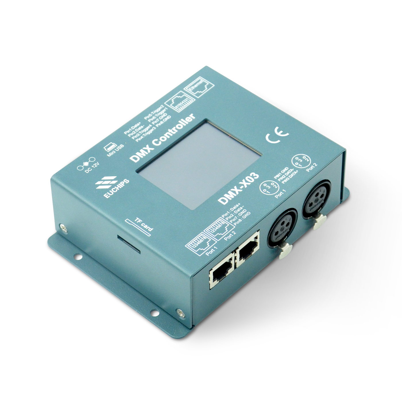
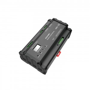
5VDC 1024ch DMX Master Controller DMX-X03
Summary
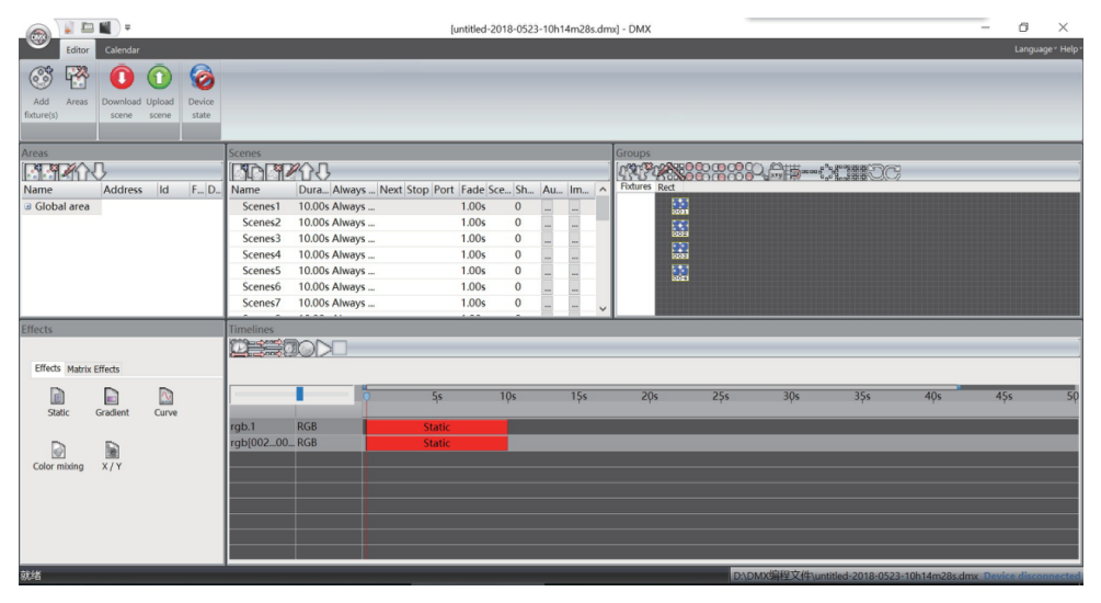
DMX-X03 is a full-color LED DMX control system which focuses on indoor and outdoor decorative lighting, which can be used stand alone or with computer. It comprises scene-edit software. You can edit various lighting effects by downloading the programme which edit according
to your special requirement from your PC.This control system can fulfill 256 grey levels for each R,G,B color,totally 16.77 million real full-color. The software has been developed specially for architectural lighting and features easy to use effects which can be dropped onto timelines, along with multi-zone and synchronization allowing you to program a project with multiple rooms and areas with ease
Technical Paramaters
Input Voltage : 5V DC, 0.15A-1A (by USB) / 12V DC input on DC connectors
Power Consumption : < 2W
Connection :USB 2.0,Ethernet XLR3
Output connector : RJ45 DMX512(1990)
Transmission signal : 1024 DMX channels
Output channels : 1024 DMX channels
Stand Alone mode : Wallwashing light, Tube light, Cube light,etc.
Lamp type :Windows XP/Vista/Seven/Win10 32/64 1Ghz CPU, 512 MB RAM
OS Requirement : Euchips X-DMX
PC Software : IP20, -25℃ to 70℃
Environment :
Power supply mode: WHEN DMX-X03 works independently, 12V power must be used.
Usb power supply will be insufficient and normal operation will be impossible
Dimension(mm)

Top Face Of Interface

Behind Face Of Interface

LCD Interface introduction
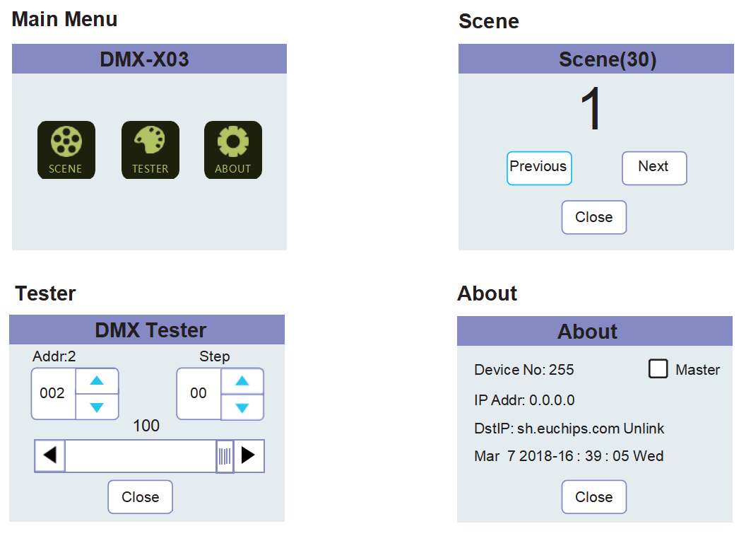
Default Mode
Note:factory default setting with 30 kinds of prodcut models , if use software to edit and download it , the following sceces will be covered.
|
NG. |
Mode |
NG. |
Mode |
|
1 |
Red |
16 |
Six color flash |
|
2 |
Green |
17 |
RGB flash |
|
3 |
Blue |
18 |
RG flash |
|
4 |
Yellow |
19 |
RB flash |
|
5 |
Cyan |
20 |
GB flash |
|
6 |
Purple |
21 |
R flash |
|
7 |
White |
22 |
G flash |
|
8 |
Seven color fade |
23 |
B flash |
|
9 |
Full color fade |
24 |
Seven color strobe |
|
10 |
Rainbow changing |
25 |
Six color strobe |
|
11 |
Water flowing |
26 |
RGB strobe |
|
12 |
Tail chase |
27 |
RG strobe |
|
13 |
Color stack |
28 |
RB strobe |
|
114 |
Chase(Blue,Purple) |
29 |
GB strobe |
|
15 |
White flash |
30 |
White strobe |
Live Use With Computer
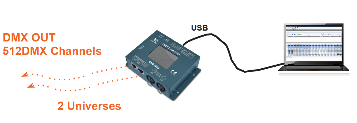
Stand Alone Use

Master/slave Mode

Configuration of the master/slave
When multiple devices are cascaded, all devices need to be connected to the same local area network ( i.e., the same router ) with network cables. Each device will automatically acquire an independent IP address in the local area network. as shown in the following figure, you can see in the about interface, when all the IP addresses of the devices are acquired, you can select any one of the devices to set as the master ( with the master option √ ), and the other devices will be set as the slave control by default. the master will trigger the operation and then pass it to the slave control. However, the split control is out of sync with the master control when controlling the scene to be played by itself. Therefore, the sub-control can start and play different scenes. The main controller is like an ordinary remote controller to control other sub - controllers.
Note: when setting up the master control on the LAN, only one of them can be selected as the master control, and not more than one can be selected at the same time.

RS485 trigger function
RS485 bus triggering scene function
The third party device can control the device through the RS485 bus. Baud rate: 9600, no check,1bit stop. Receive and send names using fixed length commands, length 15Byte。
1.1 Bus support command
| Seriel number |
Command |
OP Code |
Description |
Memory function |
| 1 |
Return value switch |
0x01 |
Set whether DMX - x03 has ACK |
NVM,Memory function |
| 2 |
Resume\Pause |
0x02 |
Pause playback and resume playback | RAM,Boot defaults to continue |
| 3 |
Scene call |
0x03 |
Scene call |
NVM,Memory function |
| 4 |
ON\OFF control |
0x04 |
On / off control |
RAM,Default ON |
| 5 | Get \ set device number |
0x05 |
Stand-alone connection settings |
NVM,Memory function |
NVM:Nonvolatile memory, power down memory; RAM:Loss of memory, power failure to enter the default state;
1.2 485 Bus command format
->DMX-X03
| Byte0 | Byte1 |
Byte2 |
Byte3 | Byte4 | Byte5 | Byte6 | Byte7 |
| 'E' | 'U' |
Device code |
Device No | CMD | SubCMD | Para0 | Para1 |
| Byte8 | Byte9 |
Byte10 |
Byte11 | Byte12 | Byte13 | Byte14 | |
| Para2 | Para3 |
Para4 |
Para5 | Para6 | Para7 | CRC |
<-DMX-X03
| Byte0 | Byte1 |
Byte2 |
Byte3 | Byte4 | Byte5 | Byte6 | Byte7 |
| 'E' | 'U' |
Device code |
Device No | ACKCMD | SubCMD | Para0 | Para1 |
| Byte8 | Byte9 |
Byte10 |
Byte11 | Byte12 | Byte13 | Byte14 | |
| Para2 | Para3 |
Para4 |
Para5 | Para6 | Para7 | CRC |
Device NO: 0xFF,Broadcast ALL Device; Check Sum the calculation function is as follows:
unsigned char CRCCalc(void* DataBuf,unsigned char Length)

1.1 RS485Bus command description:
1.1.1 Return value switch command(0x01): CMD:0x01
| Byte0 | Byte1 | Byte2 | Byte3 | Byte4 | Byte5 | Byte6 | Byte7 |
| 'E' | 'U' | Device code | Device No | CMD | SubCMD | 0 | 0 |
| Byte8 | Byte9 | Byte10 | Byte11 | Byte12 | Byte13 | Byte14 | |
| 0 | 0 | 0 | 0 | 0 | 0 | CRC |
CMD: 0x01,SubCMD: 0x00,ACK OFF,0x01,ACK ON; ACKCMD: 0x81
| Byte0 | Byte1 | Byte2 | Byte3 | Byte4 | Byte5 | Byte6 | Byte7 |
| 'E' | 'U' | Device code | Device No | ACKCMD | Status | 0 | 0 |
| Byte8 | Byte9 | Byte10 | Byte11 | Byte12 | Byte13 | Byte14 | |
| 0 | 0 | 0 | 0 | 0 | 0 | CRC |
Status: 0x0 CMD Failure,0x01 CMD Success
1.1.2 Resume\Pause command(0x02): CMD:0x02
| Byte0 | Byte1 | Byte2 | Byte3 | Byte4 | Byte5 | Byte6 | Byte7 |
| 'E' |
'U' |
Device code | Device No | CMD | SubCMD | 0 | 0 |
| Byte8 | Byte9 | Byte10 | Byte11 | Byte12 | Byte13 | Byte14 | |
| 0 | 0 | 0 | 0 | 0 | 0 | CRC |
SubCMD: 0x01 Suspend, 0x00, Run
Without Memory function, default status is run, after power on
ACKCMD: 0x82
| Byte0 | Byte1 | Byte2 | Byte3 | Byte4 | Byte5 | Byte6 | Byte7 |
| 'E' | 'U' | Device code | Device No | ACKCMD | Status | 0 | 0 |
| Byte8 | Byte9 | Byte10 | Byte11 | Byte12 | Byte13 | Byte14 | |
| 0 | 0 | 0 | 0 | 0 | 0 | CRC |
Status: 0x0 CMD Failure,0x01 CMD Success
1.3.4 ON\OFF control(0x04): CMD:0x04
| Byte0 | Byte1 | Byte2 | Byte3 | Byte4 | Byte5 | Byte6 | Byte7 |
| 'E' | 'U' | Device code | Device No | CMD | SubCMD | 0 | 0 |
| Byte8 | Byte9 | Byte10 | Byte11 | Byte12 | Byte13 | Byte14 | |
| 0 | 0 | 0 | 0 | 0 | 0 | CRC |
SubCMD: 0x00 ON,0x01 OFF Without Memory function, default status is ON, after power on
485 command attention
The 485 instruction jump scenario is sent in broadcast mode by default. If change the device number, please look at the 485 bus command instructions to get/set device number (0 x05) instructions.
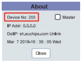
Change after the Device number can check Device in the About No number, a controlled Device if separate jump scene Byte3 byte into a corresponding
Device No value (hexadecimal) and recalculate the CRC check code.Calculating a checkmark error does not trigger the scenario that requires a jump.The absence of Device No does not trigger the scene requiring a jump.
ACKCMD:0x84
| Byte0 | Byte1 | Byte2 | Byte3 | Byte4 | Byte5 | Byte6 | Byte7 |
| 'E' | 'U' | Device code | Device No | ACKCMD | Status | 0 | 0 |
| Byte8 | Byte9 | Byte10 | Byte11 | Byte12 | Byte13 | Byte14 | |
| 0 | 0 | 0 | 0 | 0 | 0 | CRC |
Status: 0x0 CMD Failure,0x01 CMD Success
1.3.4 Get \ set device number(0x05):
It is used when a single machine is connected , and is used for setting equipment numbers, so that different equipment can be distinguished when multiple machines are used together.
CMD:0x05,
| Byte0 | Byte1 | Byte2 | Byte3 | Byte4 | Byte5 |
Byte6 |
Byte7 |
| 'E' | 'U' | Device code | Device No | CMD | SubCMD |
Para0 |
0 |
| Byte8 | Byte9 | Byte10 | Byte11 | Byte12 | Byte13 |
Byte14 |
|
| 0 | 0 | 0 | 0 | 0 | 0 |
CRC |
Device No:0xFF,Broadcast or specify equipment number modification; SubCMD:
0x00 : Get device number,Para0: 0x00 0x01: Set device number,Para0:Device number
ACKCMD:0x85
| Byte0 | Byte1 | Byte2 | Byte3 | Byte4 | Byte5 | Byte6 | Byte7 |
| 'E' | 'U' | Device code | Device No | CMD | Status | 0 | 0 |
| Byte8 | Byte9 | Byte10 | Byte11 | Byte12 | Byte13 | Byte14 | |
| 0 | 0 | 0 | 0 | 0 | 0 | CRC |
Status: 0x0 CMD Failure,0x01 CMD Success Device NO:Updated Device NO
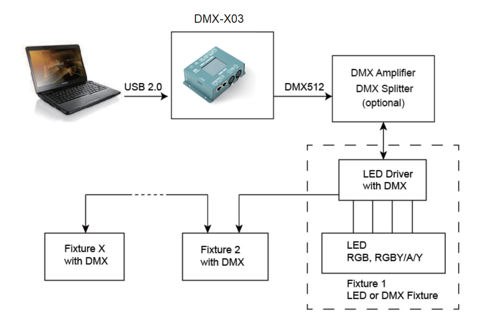
Recommended DMX512 Installation
Software
EuchipsX-DMX has evolved over the years for architectural lighting control. It only requires a few minutes to setup the software and gain full control of any kind of lighting.
